Draw Circle at a Point in Wpf Xaml Using Path
A basic graphic object of WPF Shape
The base form of WPF graphics is Shape, and all WPF graphics classes are inherited from Shape. WPF provides many ready-made Shape Object. All shape objects are derived from Shape Form inheritance. Available shape objects include Ellipse, Line ,Path,PolygonPolyline and Rectangle. Shape Objects share the following common backdrop.
-
Stroke : describes how the shape outline is drawn.
-
StrokeThickness : describes the thickness of the shape contour.
-
Make full : describes how the interior of a shape is fatigued.
-
Information attributes used to specify coordinates and vertices, measured in device independent pixels.
Considering they are derived from UIElement Shape objects tin be used in panels and most controls. The Sail Panels are a particularly good choice for creating complex graphics because they support the absolute positioning of their children.
The Line Class enables you to describe a line betwixt two points. The following case shows several ways to specify line coordinates and stroke attributes.
<Canvass Height="300" Width="300"> <!-- Draws a diagonal line from (ten,x) to (50,50). --> <Line X1="ten" Y1="10" X2="50" Y2="l" Stroke="Black" StrokeThickness="4" /> <!-- Draws a diagonal line from (10,10) to (50,50) and moves it 100 pixels to the right. --> <Line X1="10" Y1="ten" X2="50" Y2="50" StrokeThickness="4" Canvas.Left="100"> <Line.Stroke> <RadialGradientBrush GradientOrigin="0.v,0.five" Center="0.v,0.5" RadiusX="0.5" RadiusY="0.v"> <RadialGradientBrush.GradientStops> <GradientStop Color="Red" Kickoff="0" /> <GradientStop Color="Blue" Offset="0.25" /> </RadialGradientBrush.GradientStops> </RadialGradientBrush> </Line.Stroke> </Line> <!-- Draws a horizontal line from (10,lx) to (150,threescore). --> <Line X1="x" Y1="60" X2="150" Y2="60" Stroke="Blackness" StrokeThickness="4"/> </Canvas>
// Add a Line Element myLine = new Line(); myLine.Stroke = Organization.Windows.Media.Brushes.LightSteelBlue; myLine.X1 = ane; myLine.X2 = fifty; myLine.Y1 = one; myLine.Y2 = 50; myLine.HorizontalAlignment = HorizontalAlignment.Left; myLine.VerticalAlignment = VerticalAlignment.Heart; myLine.StrokeThickness = 2; myGrid.Children.Add(myLine);
The following image shows the rendered Line.
although Line Class does provide backdrop Fill , only setting it does not piece of work, Line Considering at that place is no area.
A straight line is the simplest effigy. Utilise X1 and Y1 to set the starting indicate coordinate, and X2 and Y2 to set the ending point coordinate. Past controlling the coordinates of the starting point and the stop bespeak, parallel and staggered effects can exist accomplished. The data type of the Stroke attribute is Brush.
Allow'south take some other example:
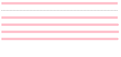
<!--StrokeThickness: The thickness of figure outline; StrokeDashArray: The style of the dotted line gap of the shape outline; StrokeStartLineCap/StrokeEndLineCap: Beginning of straight line/The graphic style of the end. The attribute values are Apartment,Round,Foursquare,Triangle--> <Line X1="x" Y1="20" X2="500" Y2="20" Stroke="Pink" StrokeThickness="10"/> //Stroke is the color and stroke thickness is the width of the line <Line X1="10" Y1="fifty" X2="500" Y2="50" Stroke="Black" StrokeDashArray="3" StrokeThickness="ane"/> //strokeDashArray is a dashed gap <Line X1="10" Y1="fourscore" X2="500" Y2="80" Stroke="Pink" StrokeEndLineCap="Flat" StrokeThickness="10"/> <Line X1="x" Y1="110" X2="500" Y2="110" Stroke="Pink" StrokeEndLineCap="Round" StrokeThickness="10"/> <Line X1="10" Y1="140" X2="500" Y2="140" Stroke="Pink" StrokeEndLineCap="Foursquare" StrokeThickness="10"/> <Line X1="ten" Y1="170" X2="500" Y2="170" Stroke="Pink" StrokeEndLineCap="Triangle" StrokeThickness="10"/>
The results are as follows:
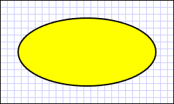
Another mutual shape Ellipse Yes. By definition Ellipse shape Width and Elevation Property creation. To draw a circle, specify Ellipse his WidthHeight Equal to a value. Rectangle, consisting of Stroke and Fill.
<Ellipse Fill up="Yellow" Height="100" Width="200" StrokeThickness="ii" Stroke="Black"/>
using System; using System.Windows; using System.Windows.Controls; using System.Windows.Media; using System.Windows.Shapes; namespace SDKSample { public fractional class SetBackgroundColorOfShapeExample : Page { public SetBackgroundColorOfShapeExample() { // Create a StackPanel to contain the shape. StackPanel myStackPanel = new StackPanel(); // Create a scarlet Ellipse. Ellipse myEllipse = new Ellipse(); // Create a SolidColorBrush with a red colour to fill the // Ellipse with. SolidColorBrush mySolidColorBrush = new SolidColorBrush(); // Describes the brush's color using RGB values. // Each value has a range of 0-255. mySolidColorBrush.Color = Color.FromArgb(255, 255, 255, 0); myEllipse.Fill = mySolidColorBrush; myEllipse.StrokeThickness = 2; myEllipse.Stroke = Brushes.Black; // Ready the width and height of the Ellipse. myEllipse.Width = 200; myEllipse.Height = 100; // Add the Ellipse to the StackPanel. myStackPanel.Children.Add(myEllipse); this.Content = myStackPanel; } } } The following paradigm shows the rendering Ellipse An instance of.
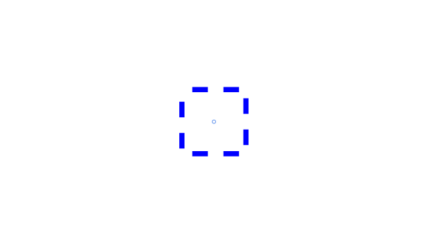
Wait at the following example, drawing a rectangle into a rounded rectangle
<Rectangle Width="200" Height="200" StrokeDashArray="3" Make full="Transparent" Stroke="Blue" StrokeThickness="fifteen" StrokeDashCap="Flat" StrokeDashOffset="100" StrokeEndLineCap="Triangle" StrokeMiterLimit="10" StrokeLineJoin="Round"/>
Dashed lines are besides chosen nuance patterns
The StrokeDashArray property contains a group of double type values, which identify the length of the dotted line and the solid line. A number represents the virtual office and real part of the same size, two numbers represent the minor size of the virtual part and the real part, and more one represents the first, 2d and tertiary paragraph
The RadiusX and RadiusY attributes need to use a combination of angles to represent the bending, which does non piece of work if fix separately. RadiusX represents the curvature of the 10-axis angle, and RadiusY represents the curvature of the Y-centrality angle.
The StrokeDashCap property is used to set the shape of the dashed line. If there is no dashed line, it will not take effect
StrokeDashOffset indicates the starting distance and beginning of the dash
StrokeEndLineCap sets the shape at the beginning or end. Airtight curves are invalid
The ratio of the stroke length to the miter stroke limit. This value is e'er a positive number greater than or equal to 1.
Polygon polygon,
Consider the following example:
<Polygon Points="100,150 400,150 140,320 250,50 360,320" StrokeThickness="two" Stroke="Pinkish"/>
The Points attribute represents a collection of polygon Points.
IsClosed specifies whether the last signal of the polygon is airtight to the first bespeak. To be a polygon. Should be set to true in general
The ArcRoundness holding specifies how far from the end of the LineSegment to kickoff the bend, and is commonly used with useroundness pct.
The useroundness percentage property specifies whether the ArcRoundness value is a pct or a fixed value.
For example, if ArcRoundness is set up to 10 and useroundness percentage is set to imitation, the curve will outset at 10 from the cease of the line segment. If apply roundness percentage is set to true. The curve starts at 10% of the terminate of the line.
Polyline is a multi line type, which is composed of a number of straight lines connecting the head and tail.
Consider the following example:
<Polyline Points="50,200 100,80 200,80 150,120" StrokeThickness="2" Stroke="Pink"/>
exist careful:
Polyline draws a broken line at a pocket-size bending (such equally a few degrees). One of the two lines forming the corner will exceed, and the smaller the angle, the more obvious.
The problem is as follows:
You tin use custom shape to solve this problem. When rewriting DefiningGeometry, you can write the post-obit code:
using (StreamGeometryContext context = sg.Open())
{
context.BeginFigure(Points[0], true, false);
foreach (Bespeak p in Points)
{
context.LineTo(p, true, truthful);
}
}
2. Using paths and geometry
Path path can combine bones elements such every bit lines, arcs and curves to form more complex graphs. These curves and shapes use Geometry Object. To utilise Path , create Geometry And utilise it to set Path Properties of the object Data . WPF provides ii classes to draw the path data: ane is StreamGeometry and the other is PathFigureCollection. In that location are many Geometry Objects are bachelor for option. RectangleGeometryEllipseGeometry and LineGeometry Class describes relatively unproblematic shapes. To create more complex shapes or create curves, use the PathGeometry.
The most of import aspect of Path: Data. See the following example:
<! -- Thousand: move to kickoff point C: cubic Bezier curve -- >
<Path Stroke="Red" StrokeThickness="two" Data="1000 240,240 C 160,80 320,80 240,240"/>
<Path x:Name="PathFillColor" Fill="{TemplateBinding Holding=Button.Background}"> <Path.Information> <PathGeometry> <PathFigure StartPoint="i,24" IsClosed="True"> <LineSegment Point="35,58"/> <ArcSegment Size="55,twenty" Point="59,48" SweepDirection="Clockwise"/> <LineSegment Betoken="59,i"/> <ArcSegment Size="eighty,lxxx" Signal="one,24" SweepDirection="Counterclockwise"/> </PathFigure> </PathGeometry> </Path.Information> </Path> WPF provides two classes to draw the path data: 1 is StreamGeometry and the other is PathFigureCollection.
<Path Stroke="Black" Data="Thou 100,240 C 510,300 fourscore,100 300,160 H40 v80" />
Is the XAML code representation of StreamGeometry, which is besides the virtually concise representation.
<Path Stroke="Black" StrokeThickness="1" Fill="#CCCCFF"> <Path.Information> <PathGeometry Figures="M ten,100 C ten,300 300,-160 300,100" /> </Path.Information> </Path>
This is done using the XAML code representation of the pathfigure drove.
These two methods can attain the same display outcome. When to employ StreamGeometry and pathfigure collection?
Mostly, when y'all create a path and you no longer demand to modify it, you tin apply the StreamGeometry method. If y'all need to modify the path value, you can use the PathFigureCollection method (here is PathGeometry).
The significant of the string "M 100240 C510300 80100300160 H40 V80" is explained beneath.
It can be explained in four cases
ane. Motion Command (M): K starting point or M starting point
For example, m 100240 or thousand 100240
When using uppercase one thousand, it ways absolute value; when using lowercase m, it indicates the value relative to the previous point, if the previous point is not specified, employ (0,0).
2. Draw command:
We can depict the post-obit shapes:
(i) Line(Fifty)
(two) Horizontal line(H)
(3) Vertical line(V)
(iv) Cubic Bezier bend(C)
(5) Quadratic Bezier curve(Q)
(6) Polish cubic Bezier curve(S)
(seven) polish quadratic Bezier curve(T)
(eight) Elliptical arc: elliptical Arc(A)
The English letters in brackets after each of the above shapes are the upper example form of the command abbreviation, but yous can also use lower case. The difference between using uppercase and lowercase is that upper case is accented and lowercase is relative. For example, 50 100 and 200 L 300400 stand for a straight line from the absolute coordinate point (100200) to another absolute coordinate betoken (300400). And 50 100, 200 L 300400 means a straight line from the coordinate point (100200) calculated from the previous point (0,0 coordinate point past default if not specified) to the coordinate point (300400).
When we reuse the same type, nosotros tin can omit the previous command. For example: fifty 100, 200 L 300 400, abbreviated as l 100, 200, 300, 400.
<Path Stroke="Black" StrokeThickness="1" Information="Grand 10,10 100,10 100,xl Z M 10,100 50 100,100 100,50 Z" />
Here is a Z command that you haven't seen nonetheless. It is a close Command, which means to close the specified shape, that is, the head and tail points are continued to form a closed area.
Drawing instruction format syntax:
(i) Line(50)
Format: l end point coordinate or: l cease point coordinate.
For example, l 100100 or l 100 100. Coordinate values can be in the form of 10,y (separated by commas in the centre) or x,y (separated past one-half a space in the middle).
(two) Horizontal line(H): draws a line from the current point to the specified x coordinate.
Format: h x value or h x value (10 is System.Double Value of blazon)
For example: H 100 or H 100, or H 100.00 or H 100.00.
(3) Vertical line(Five): draws a line from the current indicate to the specified y coordinate.
Format: v y value or v y value (y is System.Double Type)
For example: V 100 or y 100, or V 100.00 or 5 100.00.
(4) Cubic Bezier bend(C): draws a cubic Bezier curve from the current signal to the specified cease point by specifying two command points.
Format: c get-go command indicate second control point finish point or c beginning control point second control signal end bespeak
For example: C 100200 200400 300200 or C 100200 200400 300200
Among them, point (100200) is the beginning control point, point (200400) is the second command point and point (300200) is the end point.
(5) Quadratic Bezier curve(Q): draws a quadratic Bezier curve from the current point to the specified cease point through a specified control point.
Format: q control point finish point or q command point terminate indicate
For example: Q 100200 300200. Among them, point (100200) is the control indicate and point (300200) is the end point.
(6) Polish cubic Bezier curve(S): Smooth cubic Bezier curve(S): controls the Bezier curve from the electric current point to the specified point "smoothly" through a specified betoken.
Format: due south command indicate end bespeak or south control point end indicate
For example: s 100200 200300
(7) smoothen quadratic Bezier curve(T): similar to smooth cubic Bezier curve.
Format: t control point end betoken or t control point end signal
For case: t 100200 200300
(8) Elliptical arc: elliptical Arc(A): draws an arc betwixt the electric current signal and the specified end bespeak.
Dimension A arc rotation angle value mark the positive and negative angle of the dominant arc marker the cease indicate
Or:
a dimension arc rotation angle value marker positive and negative angle mark finish point of dominant arc
Size: System.Windows.Size Blazon to specify the radius value in the 10 and Y directions of the ellipse arc.
Rotation angle: Organisation.Double Type.
rotationAngle: the rotation bending value of the elliptical arc.
Is largearcflag: whether it is a dominant arc. If the angle of the arc is greater than or equal to 180 degrees, it is ready to 1; otherwise, it is 0.
sweepDirectionFlag: ready to 1 when drawing in positive direction, otherwise 0.
End betoken: Organisation.Windows.Point Type.
three. Shut control: used to connect the first and final points of a graph with a straight line to grade a closed expanse.
In Z or Z.
The difference betwixt graphic cartoon and geometric cartoon:
Graphics objects can be independently, and can describe specific graphics independently.
Geometry object has no specific shape, information technology needs to rely on an object element and tin not exist directly presented on the drawing board
Geometric drawing includes v kinds of objects:
LineGeometry: line geometry
Rectangle geometry: rectangular geometry
Ellipse geometry: ellipse geometry
PathGeometry: path geometry
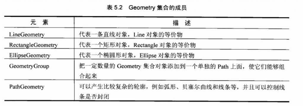
Geometry grouping: a grouping of geometric figures formed by combining several basic geometric figures
Consider the following case:
<Filigree Height="469" VerticalAlignment="Bottom"> <Grid.ColumnDefinitions> <ColumnDefinition Width="239*"/> <ColumnDefinition Width="253*"/> </Grid.ColumnDefinitions> <Grid.RowDefinitions> <RowDefinition Height="100*"/> <RowDefinition Top="100*"/> <RowDefinition Height="100*"/> <RowDefinition Height="169*"/> </Grid.RowDefinitions> <!--straight line--> <Path Stroke="Blueish" StrokeThickness="2" Grid.Column="0" Grid.Row="0"> <Path.Data> <LineGeometry StartPoint="20,forty" EndPoint="200,60"/> </Path.Information> </Path> <!--Rectangular path--> <Path Stroke="Pinkish" StrokeThickness="ii" Grid.Column="1" Grid.Row="0"> <Path.Data> <!--Rect="40,20,60,threescore" 40,20 The third digit is the width and the 4th digit is the length--> <RectangleGeometry Rect="xl,20,lx,60" RadiusX="10" RadiusY="x"/> </Path.Data> </Path> <!--Ellipse path--> <Path Stroke="Yellow" Fill="Orange" Grid.Cavalcade="0" Grid.Row="i"> <Path.Information> <EllipseGeometry Center="100,50" RadiusX="60" RadiusY="40"></EllipseGeometry> </Path.Information> </Path> <!—Geometry group--> <Path Fill="Pink" Stroke="Blood-red" StrokeThickness="2"> <Path.Data> <GeometryGroup FillRule="EvenOdd"> <EllipseGeometry Center="fourscore,lxxx" RadiusX="30" RadiusY="60"/> <LineGeometry StartPoint="xx,40" EndPoint="200,60"/> <RectangleGeometry Rect="20,20,threescore,60" RadiusX="x" RadiusY="10"/> </GeometryGroup> </Path.Data> </Path> </Grid>
Geometry class (geometric drawing) includes LineGeometry (geometric line), rectangle geometry (geometric rectangle), ellipsegeometry (geometric ellipse), GeometryGroup (geometric combination) and PathGeometry (geometric path). Information technology can describe any 2nd shape of geometry.
From the drawing indicate of view, the Geometry class and Share are similar to drawing second graphics, but at that place are important differences between the two classes. The Geometry class is lighter and more efficient than Share.
2, Geometry and Path
LineGeometry, rectangle Geometry, ellipsegeometry, GeometryGroup and PathGeometry are inherited from Geometry.
In fact, path can likewise be used as a container to permit Geometry of any Geometry shape to be included in the Path.Data Inside.
LineGeometry
The Line object like to Share is used to generate a Line. The difference is that Line uses X and Y coordinates to generate lines, while LineGeometry uses StartPoint and EndPoint to complete Line drawing.
For example:
<LineGeometry StartPoint="0,0" EndPoint="100,500" />
Rectangle geometry and ellipse geometry are similar to rectangle and ellipses in Share, which are non described here.
GeometryGroup
Sometimes some graphs need to be combined. GeometryGroup has this function, such as the post-obit example:
<StackPanel x:Name="LayoutRoot" Orientation="Horizontal" Background="AliceBlue"> <Path Fill up="Cyan" Stroke="Black" StrokeThickness="3"> <Path.Information> <!--GeometryGroup combination--> <GeometryGroup FillRule="EvenOdd"> <RectangleGeometry RadiusX="ii" RadiusY="2" Rect="80,50 200,100"></RectangleGeometry> <EllipseGeometry Center="300,100" RadiusX="80" RadiusY="60"></EllipseGeometry> </GeometryGroup> </Path.Data> </Path> <Path Fill up="Cyan" Stroke="Blackness" StrokeThickness="three"> <Path.Data> <!--GeometryGroup combination--> <GeometryGroup FillRule="Nonzero"> <RectangleGeometry RadiusX="2" RadiusY="2" Rect="80,50 200,100"></RectangleGeometry> <EllipseGeometry Eye="300,100" RadiusX="lxxx" RadiusY="60"></EllipseGeometry> </GeometryGroup> </Path.Information> </Path> </StackPanel>
The operation results are as follows:
When 2 figures cross, the FillRule property of Geometry can exist used to define the filling rules of combined figures. The FillRule property has two enumeration values (enodd) and (Zonzero)
PathGeometry
PathGeometry is the most flexible of Geometry. It can draw arbitrary 2d Geometry.
<Path Stroke="Black" StrokeThickness="1"> <Path.Data> <! -- specify Path.Information The fill for is pathgeometry -- > <PathGeometry> <! -- define the figure of PathGeometry -- > <PathGeometry.Figures> <PathFigureCollection> <! -- pathfigure represents a sub part of the geometry, a series of separately connected 2D geometric segments. IsClosed: gets or sets a value indicating whether to connect the showtime and final segments of the cartoon. > <PathFigure IsClosed="Truthful" StartPoint="l,100"> <PathFigure.Segments> <BezierSegment Point1="100,0" Point2="200,200" Point3="300,100"/> <LineSegment Point="400,100" /> <ArcSegment Size="50,l" RotationAngle="45" IsLargeArc="False" SweepDirection="Clockwise" Signal="200,100"/> </PathFigure.Segments> </PathFigure> </PathFigureCollection> </PathGeometry.Figures> </PathGeometry> </Path.Data> </Path>
The above running results provide a path syntax parser to simplify the above XAML and WPF
<Path Stroke="Black" StrokeThickness="ane" Data="1000 10,100 L 100,100 100,50 Z M 10,10 100,10 100,40 Z" />
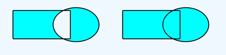
LineSegment pair
Using LineSegment object to create line object
<Path Stroke="DarkCyan" StrokeThickness="3"> <Path.Fill> <LinearGradientBrush> <GradientStop Color="Orange"/> <GradientStop Color="White" Get-go="1"/> </LinearGradientBrush> </Path.Fill> <Path.Information> <PathGeometry> <!-- Signal airtight line and specify offset position--> <PathFigure IsClosed="True" StartPoint="fifty,100"> <LineSegment Betoken="200,200" /> <LineSegment Signal="200,150" /> <LineSegment Indicate="400,150" /> <LineSegment Bespeak="400,50" /> <LineSegment Signal="200,50" /> <LineSegment Point="200,0" /> </PathFigure> </PathGeometry> </Path.Data> </Path>
Operation effect:
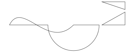
ArcSegment object
Employ ArcSegment object to draw arc elements
<Path Stroke="DarkCyan" StrokeThickness="3"> <Path.Data> <PathGeometry> <! -- arcsegment specifies the starting point of the arc -- > <PathFigure IsClosed="Fake" StartPoint="fifty,fifty"> <! -- arcsegment declares the cease signal and radian of the offset arc -- > <ArcSegment Size="280,280" Betoken="400,50" /> <! -- arcsegment declares the end indicate and radian of the second arc -- > <ArcSegment Size="xc,280" Point="550,150" /> <ArcSegment Size="50,50" Point="600,50" /> </PathFigure> </PathGeometry> </Path.Information> </Path>
Performance consequence: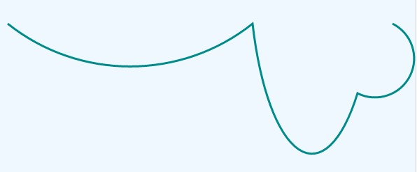
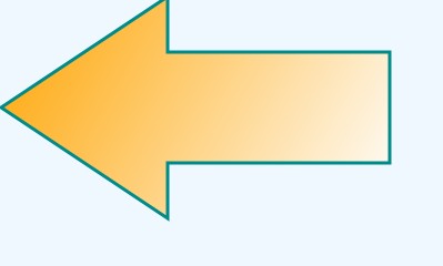
BezierSegment object
Bezier bend is fatigued by using BeezierSegment object. Bezier bend is generated by complex mathematical formula. It is used to summate how to determine the contour of a curve between ii control points. Hither is an example:
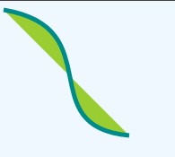
<!--Starting time drawing Bezier curves--> <Path Stroke="DarkCyan" Fill="YellowGreen" StrokeThickness="5"> <Path.Data> <PathGeometry> <!--Declare Bezier curve--> <PathFigure StartPoint="x,x"> <BezierSegment Point1="130,30" Point2="40,140" Point3="150,150"/> </PathFigure> </PathGeometry> </Path.Data> </Path>
Performance result:
Source: https://programmer.group/wpf-draws-geometry.html
0 Response to "Draw Circle at a Point in Wpf Xaml Using Path"
Postar um comentário